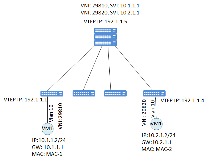
A gateway is a device that ensures communication between VXLANs identified by different VNIs and between VXLANs and non-VXLANs. With the centralized gateway routing Layer 3 gateways are configured on one device, usually on Spine layer. It is the easiest way of deploying gateways but it has some disadvantages;
- There will be a lot of ARP entries at the Spine Layer
- Forwarding path is not optimal. VMs in the same Leaf switch with different subnets will be able to communicate through the Spine.

According to topology, VM1 ad VM2 has gateways defined at the Spine layer. That means all traffic should traverse the Spine.
VTEP 1 and VTEP 2 will act as a Layer 2 gateway. They will encapsulate traffic into VxLAN tunnel and send to the gateway. (Assumption is Vlan 10 in VTEP1 is mapped to VNI 29810, and Vlan 10 in VTEP2 is mapped to VNI 29820. You can see that Vlans doesn’t have global meaning, they are locally significant.)

Arp Request from VM1 and VM2 will be sent to Spine via VxLAN tunnel. Central gateway will do de-capsulation, route packet according to inner ip header. According to routing result packets will be steered in to the related VxLAN Tunnel.
Step by step explanation of routing between 2 different VNIs;
- VM1 sends the packet to VM2.

- VTEP 1 encapsulates this packet into VxLAN header. Destination VTEP is 192.1.1.5 which is the central gateway.

- After the de-capsulation of the packet, central gateway make routing lookup and sees that it should be send from SVI which has an ip address of 10.2.1.1 and VNI of 29820. Packet is encapsulated into new VxLAN header, source VTEP is the Spine and the destination VTEP is the VTEP 2. (Source and destination mac address of user packet is also updated)

- Finally the packet will be de-capsulated and send to the VM2

Best practice for VxLAN routing and bridging is doing it with EVPN control plane. In this example I just gave the simple encapsulation and de-capsulation example.